Home
› Logic Gates Logic Diagram Symbols / Logic Gates Diagrams 101 Computing : Logic shapes like and gate, or gate, not gate and more are included here.
Logic Gates Logic Diagram Symbols / Logic Gates Diagrams 101 Computing : Logic shapes like and gate, or gate, not gate and more are included here.
Logic Gates Logic Diagram Symbols / Logic Gates Diagrams 101 Computing : Logic shapes like and gate, or gate, not gate and more are included here.. A logic gate can be represented by a block diagram as shown in figure. What is meant by logic gate? And, or, xor, not, nand, nor, and xnor. By operating on a number of. A logic gate is a switching circuit made up of a combination of transistor switches.
Logic gates symbol there are seven basic logic gates: A logic gate is a switching circuit made up of a combination of transistor switches. (click on the following equations to draw their logic gates diagrams). Pls subscribe to this channel for future tutorials (especially on. Logic gates are basically electronic circuits that perform logical functions such as addition, subtraction, multiplication etc.
Logic Gate Types Including Circuit Diagram Symbols And Uses from www.watelectronics.com Not gates or inverters have a single bit input and a single bit of output. Logic gates using the programmable logic controller (plc) is the basic thing you must learn if you want to enhance your electrical and electronics skills. Different types of ladder logic diagram that perform different logic gate functions. A circuit that works based on the logical decision and the process is called as logic gates. Normally the positive supply voltage +vs represents true and 0v represents false. It has n input (n >= 2) and one output. And gate plc ladder logic diagram: Video lectures created by tim feiegenbaum at north seattle community college.
For any digital system, it acts as an elemental building block and is able to make logical decisions.
The picture below is a logic gate. Logic gates as switching circuits. Coverting the equation to logic gates makes the following diagram. (click on the following equations to draw their logic gates diagrams). Logic gates process signals which represent true or false. For any digital system, it acts as an elemental building block and is able to make logical decisions. It is an electronic circuit having one or more than one input and only one output. Logic shapes like and gate, or gate, not gate and more are included here. It denotes the end of the chip with pin 1. Note that logic gates are not always required because simple logic functions can be performed with switches or diodes, for example Timing diagrams also show relationships between input and output conditions in a logic circuit. The and gate is so named because, if 0 is called false and 1 is called true, the gate acts in the same way as the logical and operator. What is meant by logic gate?
Logic gates definitions, types, symbols and truth tables are discussed. (click on the following equations to draw their logic gates diagrams). Logic gates act as switches in a circuit that performs logical operation. When both the inputs applied are of 0 volts both the transistors q1 and q2 are off. Let it be any form of electronics you work on, they are the most basic things to be acquainted for.
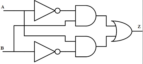
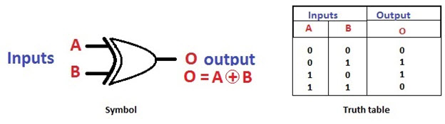
Circuit Diagram Symbols Lucidchart from d2slcw3kip6qmk.cloudfront.net Hence there is no voltage drop developed across the resistor. This post will help you understand what are logic gates, their types with brief introduction, working principle, applications. The logic diagram consists of gates and symbols that can directly replace an expression in boolean arithmetic. Only add images here if they match the images here already. The and gate is so named because, if 0 is called false and 1 is called true, the gate acts in the same way as the logical and operator. A logic gate is an idealized model of computation or physical electronic device implementing a boolean function, a logical operation performed on one or more binary inputs that produces a single binary. Pls subscribe to this channel for future tutorials (especially on. The logic circuit diagram for this exclusive gate is designed in the combination of and and or gate at the output.
In the solid state industry, they are used as the principal diagram for the design of solid state components such as computer chips.
It denotes the end of the chip with pin 1. Notice how each gate connects the variables together just like the logic blocks in the code above. The logic diagram consists of gates and symbols that can directly replace an expression in boolean arithmetic. To set the value you may select the symbol and click its floating button. When both the inputs applied are of 0 volts both the transistors q1 and q2 are off. Logic gates are basically electronic circuits that perform logical functions such as addition, subtraction, multiplication etc. Pls subscribe to this channel for future tutorials (especially on. They are used by mathematicians to help solve logical problems (called boolean algebra). This is a diagram of a not gate. A logic gate is a device that can perform one or all of the boolean logic operations and, nand, nor, not, or, xnor, and xor. It has n input (n >= 2) and one output. And gate and gate ladder logic diagram and gate symbol basic gates in plc basic gates in plc ladder logic programming best plc learning website electronic clnic exclusive nor gate exclusive or gate. As you can see two normally open type contacts are used.
Coverting the equation to logic gates makes the following diagram. It can also be done using nor logic gates in the same way. Most logic gates take an input of two binary values, and output a single value of a 1 or 0. They are used by mathematicians to help solve logical problems (called boolean algebra). The or gate performs the logical (inclusive) disjunction (true output for any true input) the output of or gate is logic high when one or more than one of its inputs is logic high.
Basic Logic Gates With Truth Tables Digital Logic Circuits from www.elprocus.com Depending on the exact configuration of inputs, you might get 2, 3, 4, or even 6 gates note the dimple in one end. In practice, each logic gate is represented by a. Logic gates are very important and they serve as the building blocks to digital logic circuits using combinational logic. That is, it performs a logical operation on one or more logical inputs, and produces a single logical the following table lists some logic gate diagram electrical symbols in our electrical diagram software. When both the inputs applied are of 0 volts both the transistors q1 and q2 are off. The diagrams below show two ways that the nand logic gate can be configured to produce a not gate. It can also be done using nor logic gates in the same way. A logic gate performs a logical operation on one or more logic inputs and produces a single logic output.
Timing diagrams also show relationships between input and output conditions in a logic circuit.
That is, it performs a logical operation on one or more logical inputs, and produces a single logical the following table lists some logic gate diagram electrical symbols in our electrical diagram software. Pls subscribe to this channel for future tutorials (especially on. The symbol is an and gate with a small circle on the output. Most logic gates take an input of two binary values, and output a single value of a 1 or 0. A logic gate is a device that can perform one or all of the boolean logic operations and, nand, nor, not, or, xnor, and xor. Logic gates are very important and they serve as the building blocks to digital logic circuits using combinational logic. They are used by mathematicians to help solve logical problems (called boolean algebra). Digital logic gates are simply a string of transistors working together to solve basic boolean functions. You have the amplifier symbol and then the zero here which is the not operation. What is meant by logic gate? This is a diagram of a not gate. Logic gates process signals which represent true or false. Use our logic gates diagram tool to create the diagrams as follow: