Switch In Circuit Diagram / Toggle Switch Circuit Diagram using 555 Timer IC - L and n indicate the supply.. This touch switch circuit diagram is built around a 555 timer by making use of the default properties of the pins of the 555 timer ic. To build a circuit you need a different diagram showing the layout of the parts on breadboard (for temporary circuits). An automatic transfer switch is often installed where a backup generator is located, so that the generator may provide 3 phase automatic changeover switch /with circuit diagram. The following diagram represents circuit established between two telephones connected by circuit switched connection. A transfer switch (ats) is an electrical switch that switches a load between two sources.
Learn vocabulary, terms and more with flashcards, games and other study tools. Circuit switching is a method of implementing a telecommunications network in which two network nodes establish a dedicated communications channel (circuit). If you notice, the power is. To build a circuit you need a different diagram showing the layout of the parts on breadboard (for temporary circuits). The circuit can also be used in variety of electronic projects to activate or deactivate the relay switch on single pulse.
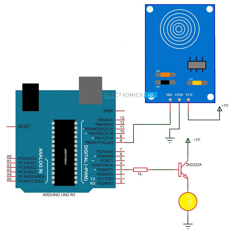
Touch Dimmer Switch Circuit using Arduino from www.electronicshub.org Wireless remote camera flash trigger schematic circuit diagram. Start studying switches in a circuit. This switch has the following features: Now don't let this be confused ok, this diagram is going to be a little more confusing but i'm showing it because this can be a very common scenario. Ct operated relay triggiring block diagram with circuit for final triggring circuit. There are 2777 circuit schematics available. A transfer switch (ats) is an electrical switch that switches a load between two sources. An on/off switch is added for the switching purpose of the relay.
Circuit diagram of the pir motion sensor light and switch based on sb0061 shown here can be used for security or corridor lighting in power saving mode.
Help for Understanding Simple Home Electrical Wiring Diagrams from img.bhs4.com Here once the dedicated path is established between the sender and receiver, it stays the same until one of the users terminates the connection. And the important feature of this circuit is that you will not. Circuit diagram is a free application for making electronic circuit diagrams and exporting them as images. In this type of switching, there is a set of switches connected with physical links. The series of light switches can work directly on the ac power network. Start studying switches in a circuit. You have a bad park neutral switch in the steering column or a problem w/ the circuit. This is a circuit for alternative sources selection.
We use the normal switch in our daily life and after a long time used to these switching system we can no more interested in that.
Circuit diagram is a free application for making electronic circuit diagrams and exporting them as images. Switched series lithium polymer lipo battery fast charger schematic circuit diagram. The circuit is very simple and the components were sold in the market. The circuit diagram for the touch on and off switches circuit is shown in the below image. The sensor circuit may contain a lc resonant oscillator or a mutual induction based circuit. Design circuits online in your browser or using the desktop application. With the help of this circuit, you can turn on and off a device by simply touching the touch plates or wire. Circuit symbols are used in circuit diagrams showing how a circuit is connected together. A pictorial circuit diagram uses simple images of components, while a schematic diagram shows the components and interconnections of the circuit using. A transfer switch (ats) is an electrical switch that switches a load between two sources. The circuit can also be used in variety of electronic projects to activate or deactivate the relay switch on single pulse. The blue boxes represent the switching offices and their connection with other switching offices. The series of light switches this time slightly different from the voltage of work.
Now don't let this be confused ok, this diagram is going to be a little more confusing but i'm showing it because this can be a very common scenario. And the important feature of this circuit is that you will not. A circuit diagram (electrical diagram, elementary diagram, electronic schematic) is a graphical representation of an electrical circuit. Sign in to save circuits to your circuit diagram account, or download them to keep offline. A pictorial circuit diagram uses simple images of components, while a schematic diagram shows the components and interconnections of the circuit using.
Light Switch Wiring Diagram | Car Construction from www.newkidscar.com You have a bad park neutral switch in the steering column or a problem w/ the circuit. There are 2777 circuit schematics available. The 12v dc supply required for the whole circuit can be fed from any standard 12v ac mains adaptor/battery. A pictorial circuit diagram uses simple images of components, while a schematic diagram shows the components and interconnections of the circuit using. The sensor circuit may contain a lc resonant oscillator or a mutual induction based circuit. When the switch is not pressed it is in a open circuit state, which current does not flow. Using the diagram, you can perform analysis of the design. This is a good solution for a unique and so interesting idea to wireless switching system to control.
A circuit diagram should be specific enough so that anyone can make the circuit just by following it.
With the help of this circuit, you can turn on and off a device by simply touching the touch plates or wire. The blue boxes represent the switching offices and their connection with other switching offices. When the switch is closed, current start flowing through the coil, and by the concept of electromagnetic induction, magnetic field is generated in the coil which attracts the. Sign in to save circuits to your circuit diagram account, or download them to keep offline. Using the diagram, you can perform analysis of the design. The circuit is very simple and the components were sold in the market. 1 x 555 timer ic. Wireless remote camera flash trigger schematic circuit diagram. A circuit diagram (electrical diagram, elementary diagram, electronic schematic) is a graphical representation of an electrical circuit. Circuit diagram is a free application for making electronic circuit diagrams and exporting them as images. O call setup phase is required o fixed route (circuit. The schematic diagram symbol for a proximity switch with mechanical contacts is the same as for a mechanical limit switch, except the note: When the switch is not pressed it is in a open circuit state, which current does not flow.